Phoenix Sound System Installation In LGB's K-28
by Jim Fowler, Grafton, Ohio (
JLFowler@aol.com)with special thanks to Cross Creek Engineering, Spencer, Ohio
________________________________________________________________________________________________________
A wonderful thing that has happened to me since my involvement in this hobby is the rare opportunities I have gotten from time to time; and this article is about one of those opportunities. How many of you wished you could take home a LGB’s, 30th Anniversary K-28? How many of you would have liked it to happen for free?
(I have included a photo study of this K-28 at the end of this article - just click here to jump to it.)Well, it happened to me. Well, sort of. Since I moonlight doing sound and DCC decoder installations for Cross Creek Engineering, I sometimes get to take my work home with me. Recently, Cross Creek owner Bob Pennock called me and asked me if I would install sound in a K-28. I must tell you I was kind of stunned, I never thought someone would want an after-market sound in one of these rare beauties; but then again, I thought the same of the LGB Shay and I have done a few of those to date! Bob told me that the new owner had actually made an inquiry for sound soon after ordering the unit earlier this year.
Cross Creek is a Phoenix Sound dealer, they sell a good number of these units and I must say that the majority of my professional sound installations for them are of Phoenix's systems. I prefer them for my personal installations and, it seems it is the choice of system for this K-28's future owner as well. Phoenix makes a sound for the K-28 specifically, so that was the soundboard model chosen for this installation.
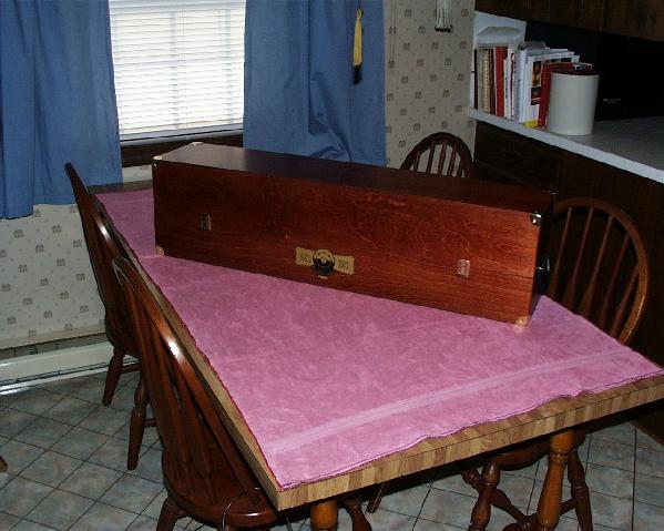
Upon picking up the unit I was immediately confronted with a small problem. As some of you may know, persons lucky enough to own the K-28 get more than just an old red and white, cardboard box to store the locomotive in when not on display. The K-28 lounges in fine style in a handcrafted, wooden carrying case measuring almost 41 inches in length. It’s a little awkward to carry inside a 1998 VW Beetle (my car!). But, with a little careful handling the K-28 was on the road to saying it's first words.
INSTALLATION PREP
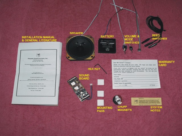
Understanding the Phoenix Big Sound 97 System
TENDER DISASSEMBLY / ASSEMBLY
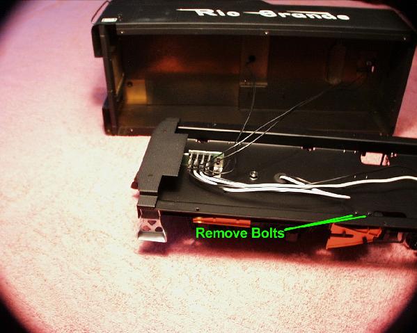
The disassembly of the tender starts by carefully inverting the tender and allowing it to rest on a towel or other type of cushioned work surface. Next, using the small
nut-driver that comes with the K-28, remove the miniature bolts holding the braking mechanism as pictured below.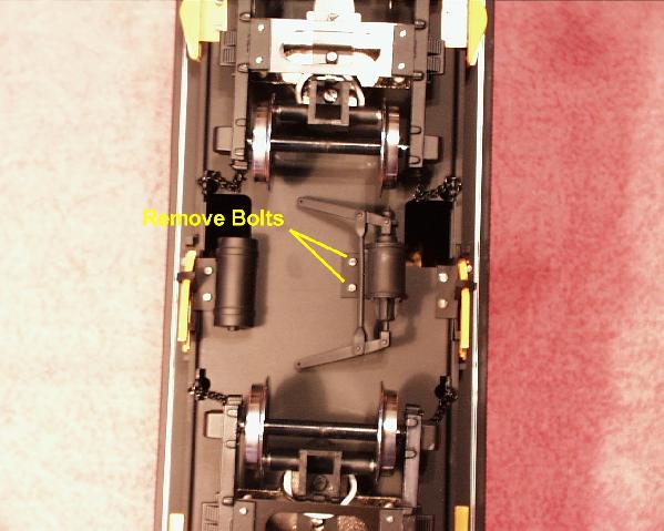
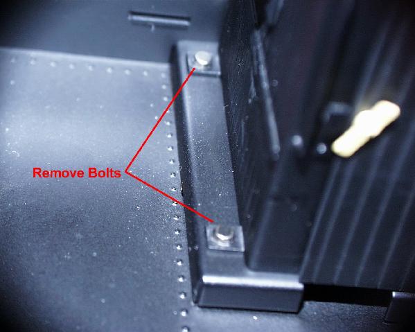
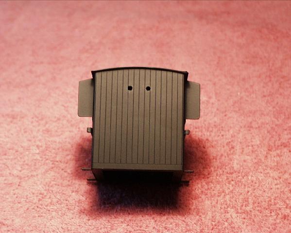
The brake mechanism and its bolts are set aside. The 6 small bolts that hold the tender's upper and lower halves together are located and removed. The picture below shows the location of the 6 bolts; there are 3 on each side.

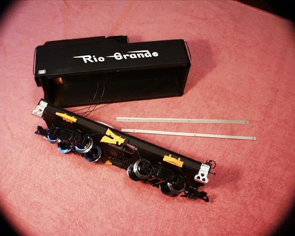
With the removal of the 6 bolts marked above, it is now possible to separate (somewhat) the upper and lower halves of the tender. As the sections are being separated, the two silver "L" channel trim strips are removed completely and set aside. The upper and lower tender sections are still connected to each other by the light wiring. The picture below shows the upper and lower sections detached from each other, the light wiring connections, and the two silver "L" channel trim strips.
Turning the lower tender section upright, you can easily view the electrical circuitry of the tender's interior. Now, the remove the tender's pneumatic brake reservoir by extracting the two bolts shown in the photo below does this action. The reservoir is set aside with the brake mechanism that was removed in an earlier step.
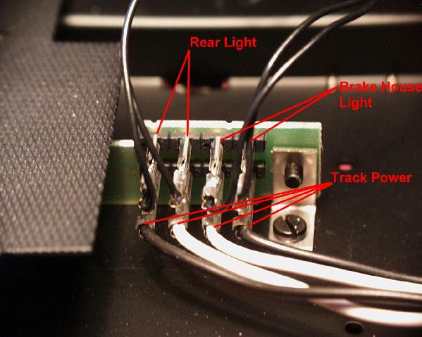
The photo below shows a close examination of the stock wiring points of the LGB tender. The two sets of lighting leads are disconnected and the upper and lower halves of the tender are now 100% separate. Note that the track power leads are left connected as originally installed.
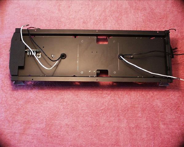
The following photo shows the completely separated halves. With the lower section free it is time to start thinking of how the sound system is going to be installed.

Please note that the procedure for putting the tender back together is simply to follow this section's operations in reverse order starting from here and working backwards (up instead of down). Overall the tenders disassembly was quick and simple with no surprises.
SYSTEM LAYOUT DESIGN
The upper section of the tender is set aside for a close examination of the lower section, and a determination of the best placement for the sound system components. The lower section's track power pickup leads are disconnected so as not to interfere with the component layout.
The most logical placement for the speaker is the center portion of the lower pan. This location allows for the best and least unrestricted sound output. The DCB97 soundboard will fit nicely in the front beside the OEM circuit board without causing any interference. The battery is best located in the rear of the lower pan. I recommend to always try to place the speaker and battery as low as possible, this will give the tender or other type of rolling stock the best possible center of gravity. Also, in contrast to the picture above, both the speaker and battery should always be centered, so not to make the tender or car lean to one side. With the component placement figured out it is time to start the actual physical installation.
SPEAKER MOUNTING
In the layout process it was determined that the speaker's best location is the center of the lower tender's pan. The pan will have to be modified for this speaker placement; holes will have to be drilled in the pan to mount the speaker and to allow the speaker to sound properly.
The picture above shows the pencil lines that were traced on the top of the pan to show the exact placement of the speaker and the four mounting holes of the speaker's flange. With these added location points and the stock features of the pan in this area, a template was created out of 1/4" graph paper. The picture below shows the finished paper template being placed on the bottom of the pan so that all the location points of the holes can be transferred to the bottom of the pan.
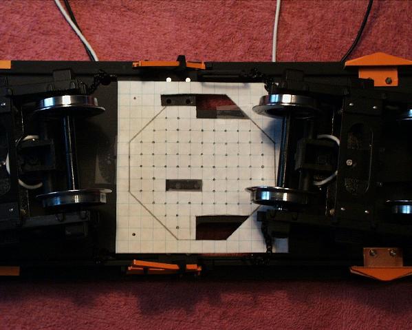
As can be seen the template has a fair amount of holes for the speaker to sound properly, but makes allowances for the stock features such as the mounting areas for the brake mechanism and reservoir. The template's hole location points are transferred to the bottom of the pan using a set punch and small hammer.
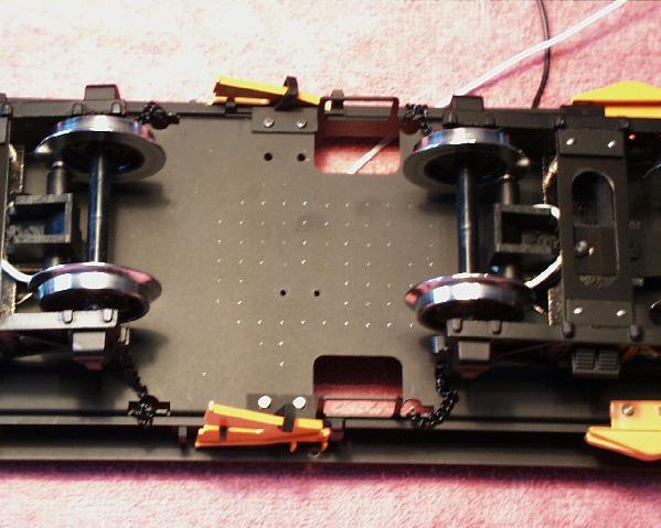
The detail pictures above and below shows the location points of the holes as they were transferred from the paper template. In transferring the points it was discovered that the pan is not composed of brass, but is made from metal. To confirm this, a magnet was used. Yes, it stuck! If this pan was made of brass then the magnet would not have stuck to it, but more important is the fact that brass does not rust like metal will - especially when holes are drilled in it. Since the possibility of this loco being exposed to long, outdoor use in climatic weather is virtually negligible, all I will have to do is dress the holes with a little paint. But, this discovery is passed on so that the new owner is aware. If this loco was slated for heavy outdoor use, then I would have had to suggest that the pan be drilled, sanded down, primed and re-painted completely. The extra service would not have been at any small cost either. It should be noted that the original paint job on the metal pan does not include a primer coat. 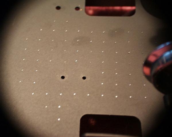
The holes were drilled using first a 1/16" drill bit followed up by a 3/16" drill bit. The pan was placed on a block of wood so it would not be distorted during drilling. The drilling operation was the most time consuming part of the whole process. Taking almost two hours to drill the 80+ holes. The result is pictured below. Please note the miss-aligned….Ah…I mean handcrafted speaker holes.
The final step to this part of the process is the actual installation of the speaker. The speaker is mounted using 4, 1/4" 4-40 screws and nuts. To avoid "speaker rattle", I usually use a small bead of sealant on the speaker edge to help affix it to plastic surfaces, this is not needed on metal because the metal surfaces are flatter and good contact is attainable.
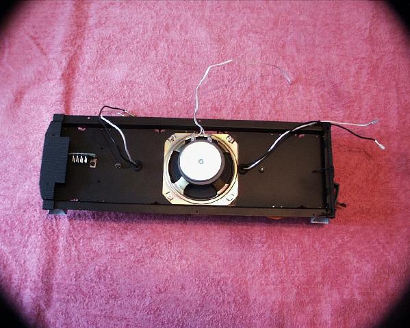
The picture above shows the installed speaker.
INSTALLATION OF WHISTLE, BELL, AND CHUFF TRIGGERS
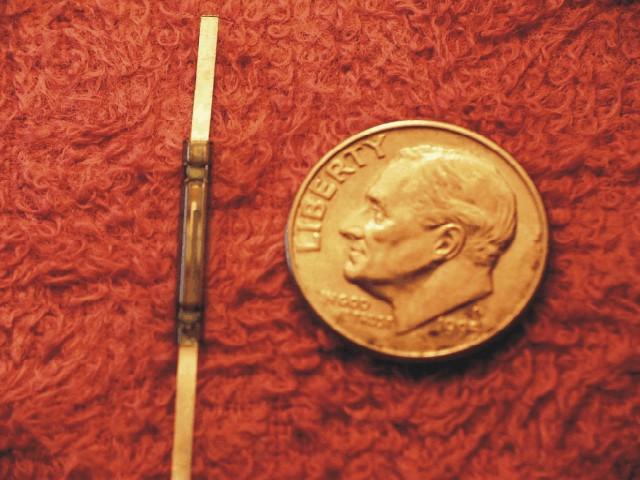
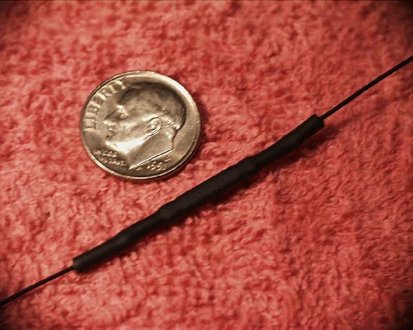
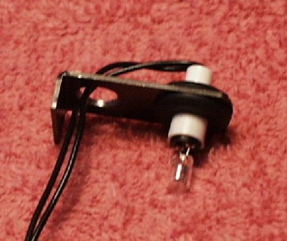
As mentioned earlier in this article, this installation will not be using the reed switch function triggers supplied by Phoenix in the sound systems kit. Instead, the small flat-style (B type) reed switches as pictured below will be used. Note the size of these units as compared to the dime, these switches are very small, but very reliable.
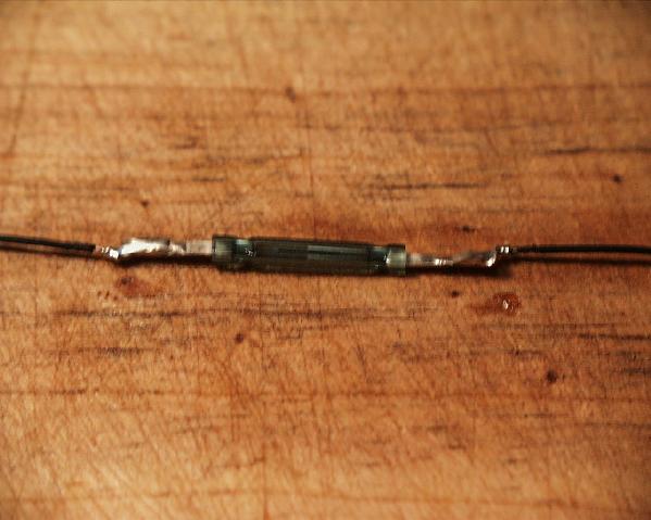
Each of the three (whistle, bell, and chuff) small reed switches is fitted with a black, 12" piece of 30 gauge, wire-wrap wire at each of the reed switch's ends, as pictured below. Using a small set of needle-nose pliers, I bend approximately 1/8" of each end of the reed switch's ends back onto itself, creating small loops at both ends of each reed switch. Next, I strip approximately 1/4" of the wire's insulation jacket from each end of the six, 12" long pieces. I then pass one end of each piece of wire through a loop at the ends of the reed switches and wrap it back around to itself, as shown in the picture below. This action basically interlocks the wire and the reed switch's lead or end to hold the two together for soldering.
The photo below shows the wire 12" leads being affixed to the reed switch using solder. Always use solder for joining these connections, never rely just on mechanical or pressure connection.
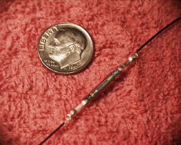
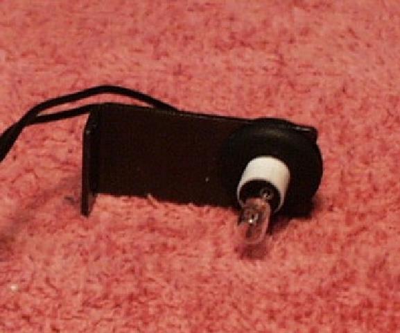
Although this style of reed switch is already sealed, a small piece of black heat-shrink is used to cover and protect the entire switch and its solder joints. The finished product is extremely small, as can be seen with its comparison to the dime in the picture. The whistle and bell triggers are made just as pictured below, but the chuff trigger differs in the fact that a lead is folded over so that both leads exit a single end of its heat-shrink sheath (sorry, I forgot to snap a picture).
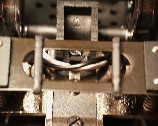
The new bell and whistle triggers are placed on the bottom-center cross-support of the tenders rear wheel truck. This cross-support is composed of a single piece of spring steel. The cross-support's strength and rigidity allow the bell and whistle triggers to be centered and their leads physically wrapped around the cross-support. A dab of Goo under the ends of each trigger help to keep it in place. Each pair of leads from both the bell and the whistle are twisted together and trailed up through the same hole, as used for the rear truck's power pick up leads. Below is a photo of the bell and whistle triggers affixed in place and their wiring passed through to the top side of the pan.
Remember, the standard configuration is the whistle is triggered from the right (passenger side - how I remember it) and the bell is triggered from the left (driver side).
The installation of the chuff trigger is a little more complicated than those for the bell and whistle triggers. The chuff trigger must be placed above an axle on the tender's front truck. This will allow magnets affixed to the axle to trigger the chuff sound as the axle rotates; the faster the loco goes, the faster the tender's axle will rotate, and thus increasing the rate of chuffs the sound system creates. The trigger is located above the axle to make it as far from the track surface as possible, this ensures that a track-magnet used to trigger a bell or whistle event will not cause a "false chuff". In this installation the chuff trigger (reed switch) is held in place with Goo. The chuff trigger leads are passed through to the upper side of the pan via the same hole as this truck's track power leads use.
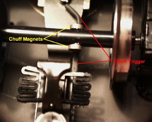
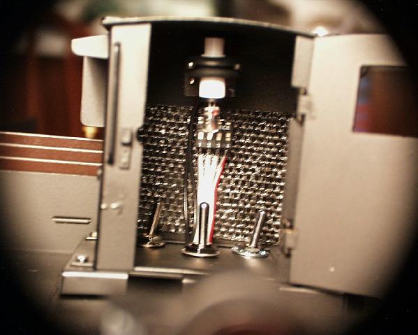
The picture above shows the normal installation and placement of the chuff trigger magnets. Normal installations use 2 chuff magnets mounted to an axle, but directly opposed or across from one another. I affix the magnets using a dab of Goo. Note that the axle should be centered in the truck and the magnets mounted directly overtop the reed switch. This alignment will allow the chuff trigger to still occur properly as the axle floats from side-to-side in normal operation. Note that for true 4 valve chuffing, some sound systems would require 4 magnets mounted in a similar manner; however, the Phoenix system gives the 4 valve effect with just the 2 chuff magnets.
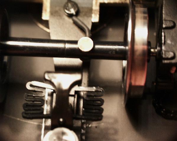
In the picture above, the axle has been rotated 90 degrees to give a little better look at the chuff trigger and the method of its operation. The installations of these alternate-style bell, whistle, and chuff triggers makes the bottom side of the tender less conspicuous and gives an overall cleaner look to the loco. Most people don't even notice the triggers at first glance while looking straight down on the inverted tender - I must point them out specifically.
At this point a conductivity test is done with an Ohm-meter and a magnet to ensure that all three triggers are functioning properly.
PLACEMENT OF SYSTEM OPERATION SWITCHES
At this point, it is time to find a spot for the option and operation switches. These are the DIP-Switch that controls the sound system's mode of operation, the volume control switch, the Canyon-Chuff switch, and the battery disconnect switch that is being added. In reading the instructions contained in Phoenix's kit, they recommend installing the switches on the bottom side of the tender. A better idea is to install all the option and operation switches inside the Brake house. This location is easier to get to and has enough space to allow all the switches to be in one area, but out of general sight.
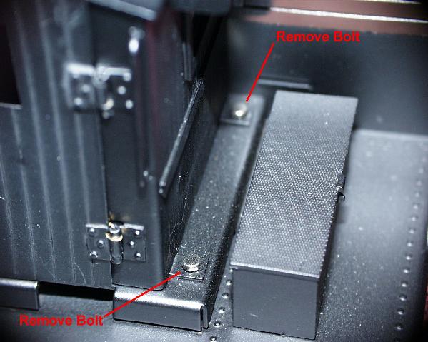
The first step is to remove the brake house from the upper section of the tender. As seen in the two pictures above, by removing the 4 bolts on the base of the brake house, the entire house structure is separated from the upper tender.
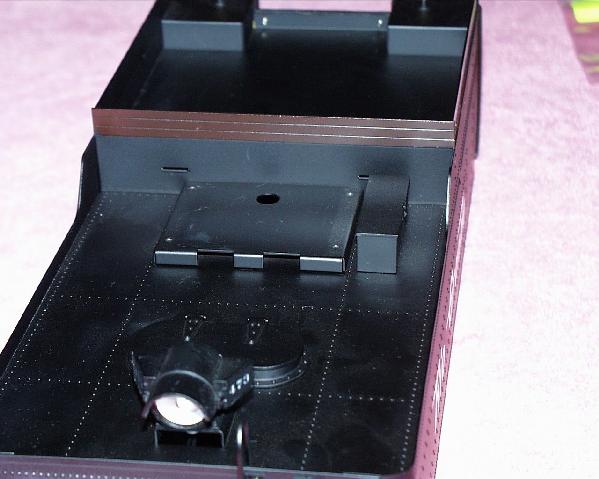
The photo above shows the upper section of the tender with the brake house removed. It is now time to layout and mark where the switches will be mounted on the brake house base. I mark the hole location points with a pencil and set them with a punch and small hammer, as shown in the picture below.
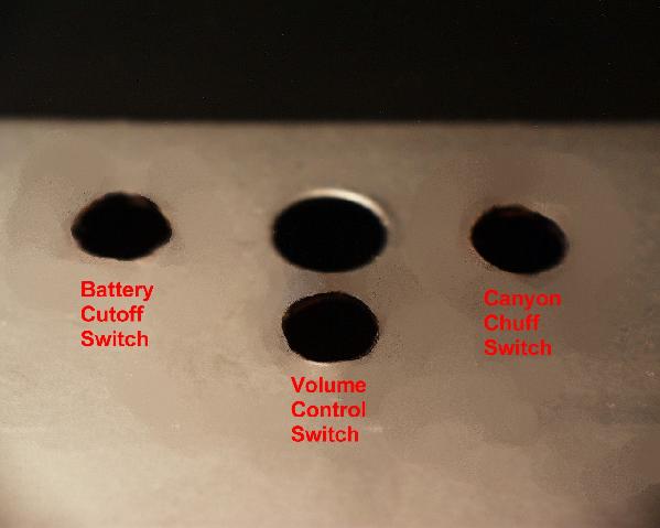
After the holes have been located, I use my battery drill to drill a 1/16" pilot hole for each of the 3 switch locations. The initial pilot holes are next opened up to a final size of 5/16". And the three switches are then installed. The pictures below show the final hole placement and identifies which switch is to be installed where.
Now, in looking closely at the brake house, a slight modification of the light-bracket will improve the interior look and help keep the light's wiring from interfering with the operation of the switches that are to be housed within the brake house itself.
To remove the brake house's light bracket, the two bolts in the front wall of the brake house were extracted. This can be seen in the picture above. Upon removal, the house itself is set aside.
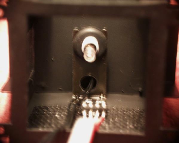
The above-left picture shows the brake house's light and light-bracket. A hole was drilled in the back portion of the light-bracket to allow the light wiring to route smoothly down the brake house's front wall. The above-right photo, shows the modified light-bracket and the light's wiring slipped through the hole. The brake house light is now ready to be re-installed.
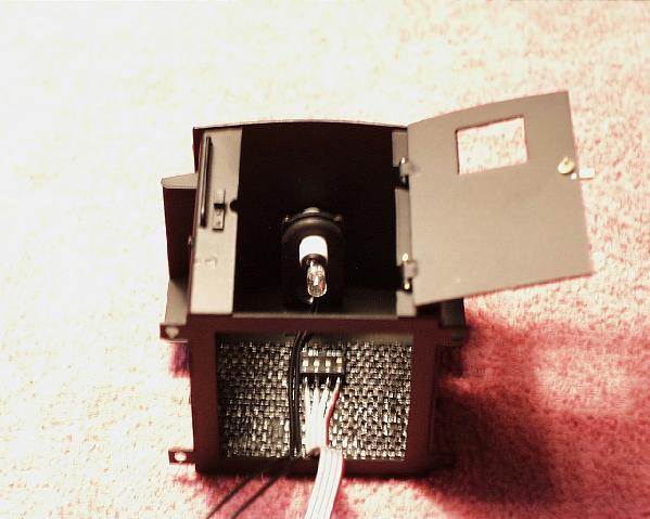
Above, the light has been re-installed and the sound system's DIP-Switch has been mounted to the front wall of the brake house. Note the black weave tape that was put on to the front wall before mounting the DIP-Switch; the material is indoor/outdoor carpet tape. This carpet tape is used in this instance to adhere and insulate the DIP-Switch from shorting against the brass of the brake house's front wall. The pictures below are close-ups of the brake house light and wiring. 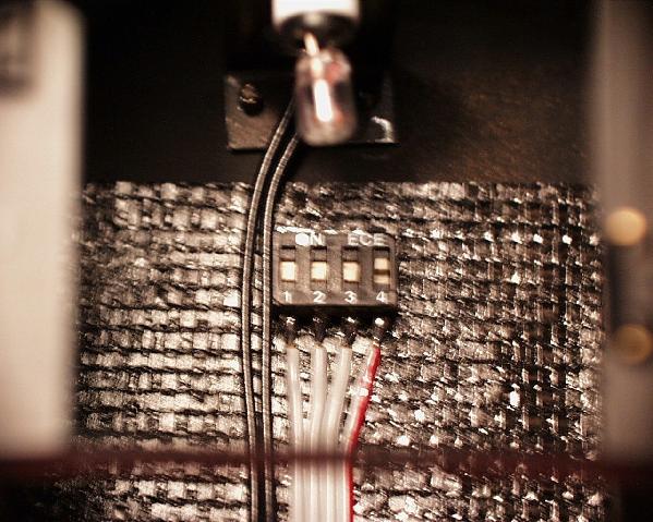
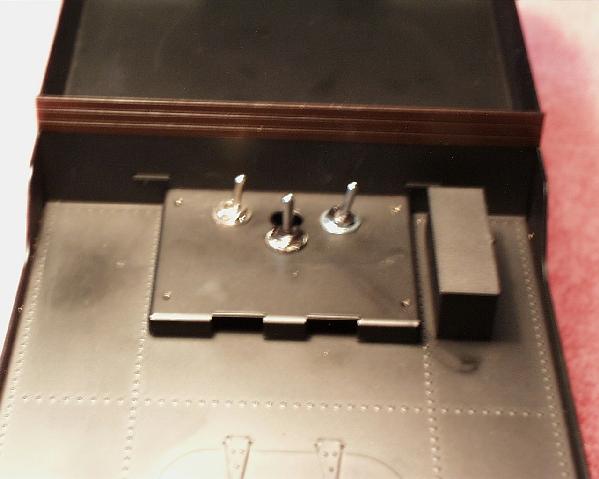
The picture below show everything assembled and the brake house re-installed. Note the switches in the floor are relatively easy to get to, and yet hidden from plain view. A nice added touch would be a brakeman figure modified to slip over the center, volume control switch -- I'll leave that up to the new owner. The DIP-Switch on the front wall almost resembles some type scale switch box, but no such animal really lived in this house.
With the installation of the mode and option switches as shown above, it is now time to mount the battery and sound board and wiring the system together.
As a follow up after the installation was completed, the illustration above was created, it shows the final placement of all the switches and their states. A copy of this illustration is provided for the future owner as reference.
BOARD AND BATTERY PLACEMENT
The next step in the installation process is the mounting of the battery and DCB-97 sound board. For mounting these types of components I use and recommend the use of indoor/outdoor carpet tape.
The indoor/outdoor carpet tape I use looks like black -sticky, woven burlap and is about 2" wide by about a 1/16" thick, and both water and cold resistant. I stopped using the foam mounting tape because it's holding power does not stand up over time under outdoor use. And when examining some older installations that were brought to me for repair, I noticed that the foam tape was also holding moisture. I also noticed greater tarnish and corrosion on the circuit board components just next to and under the foam tape than in other places. So, I looked for something else to use and found this type of carpet tape was the best at holding and did not retain moisture.
I use this carpet tape to retain components as well as to insulate objects from each other. An example is the mounting of the DCB-97 board. The tape not only holds the board firmly in place, but also insulates the board from making contact with the tender's metal, lower pan section. Contact could cause a short-circuit condition or worse - a no-sound board!
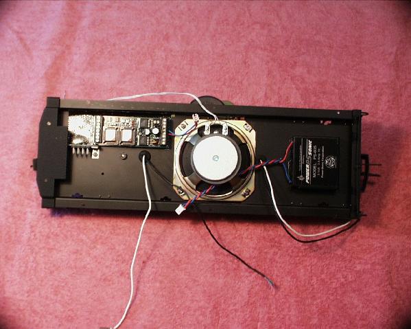
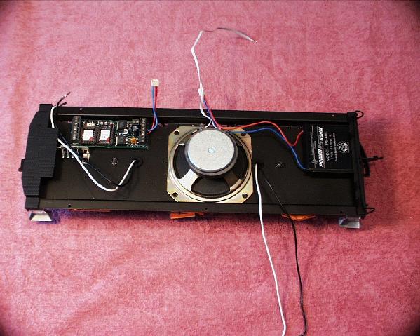
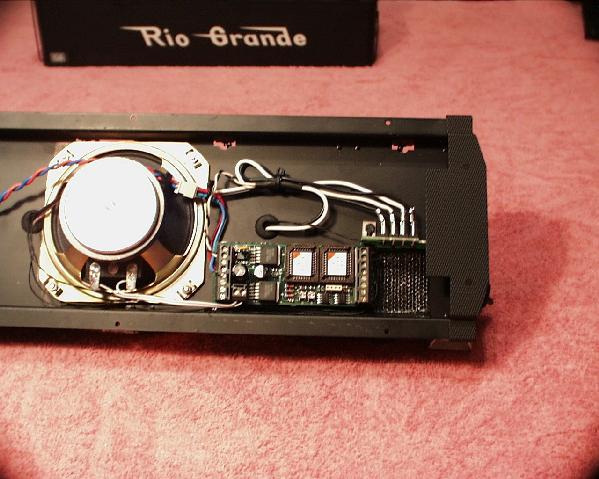
The picture above shows the battery and sound board set in place using the carpet tape mentioned above. With all the sound system's components installed, the next step is to wire together all the components following the wiring diagram shown earlier in this article. The major consideration here is where to get track power for the sound system.
The photo above shows the lower section wired and finished. The track power for the sound board comes from "Y" connections made in the front truck's power leads (the set of black and white wires pictured above). At this stage the following connections are completed: speaker, chuff trigger reed switch, bell trigger reed switch, whistle trigger reed switch, and track power. The connections to the devices mounted in the upper tender section are next. The picture below shows a little closer shot of the lower pan, and the wiring completed up to this point. Always make it a point to secure the wiring and do not let it run wild.
The picture below shows the bottom-inside view of the upper tender section. From this angle you can see the bottom of the operation switches that were installed and the switch wiring. The wiring is attached in this view, note that enough length was given to the switch wires to allow the upper and lower section of the tender to be separated easily for maintenance and inspection. As a next step, strips of indoor/outdoor carpet were placed on the inner top and sides of the tender's upper section. The tape will hold some sound insulation in place.
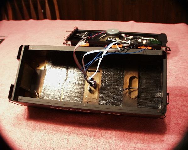
Note in the photo below the addition of fiberglass insulation to the upper tender section. The insulation will enhance the output tone by reducing the "hard-surface" area inside the sound chamber (inside of tender). The insulation used here was normal "wall insulation". But, if possible to get, I recommend using fiberglass "duct insulation" as used by heating and cooling companies for some commercial applications. Duct insulation is virtually the same thing as that expensive speaker insulation used in building custom speaker systems, but cheaper - especially if you go up and ask for if. The truth is that most generally 1 or 2 square feet of this material is more than you could use for a project and probably just a scrap to them. My brother Ed is a HVAC contractor and is kind enough to save me a piece or two when he uses the stuff on a job.
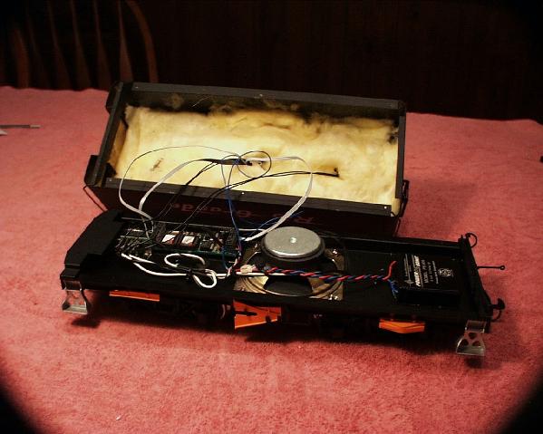
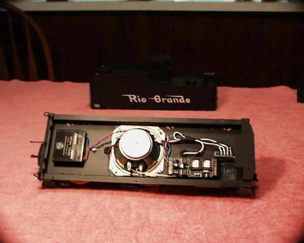
Below is the finished loco, assembled and ready for testing. Please review the section of this article covering the disassembly to understand how the tender is re-assembled.
(GO THERE NOW)
TEST RUNNING
The testing of the final assembly will require a short test drive of the K-28, engine and tender, it's hard work but I'm willing to go that extra mile (Oh Yea!).
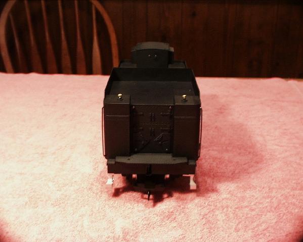
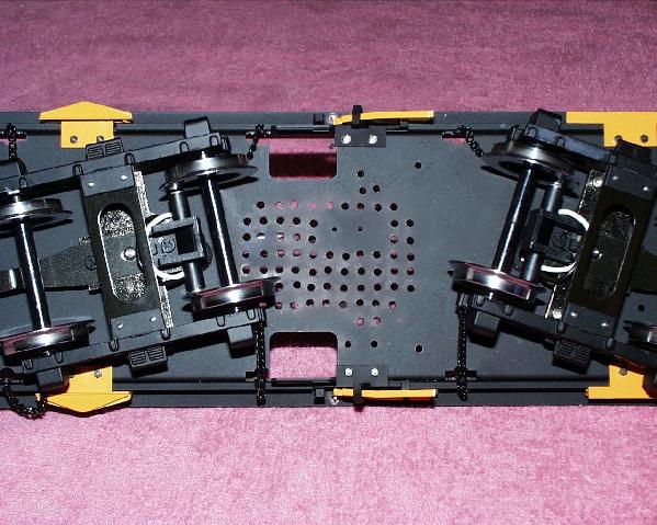
The photo above is here to talk about a basic, but important point to always check when working on or modifying rolling stock. It is important to check your work to ensure proper stance and/or weight distribution. If you load all the sound components to one side, or shift a stock weight to make way for a component installation or some other modification, you may also be effecting the stance and balance as well. So, it's very important to check stance and weight distribution of the final assembly.
Now its time to take the first test drive, and you don't need the engine yet. The tender itself is placed on a test track and the power is applied. With this initial power-on test, the state of the system's battery is determined. If the startup sound sequence kicks off strong without any choppiness to the sound, then the battery is adequately charged and the testing can proceed. If the battery is determined to be too weak to produce clear, normal sound, then it needs to be charged at this point.
The battery is charged by setting the tender down on the test track and applying between 7 and 13 volts. As a rule of thumb I use the half throttle mark when charging from a standard powered track. The voltage could be more but the internal circuitry of the sound system will cut the excessive voltage anyway; the voltage should not be less because the battery may not charge properly.
With the battery charged, the tender is rolled back-and-forth on the test track, and even over some track magnets. If everything is properly installed and sounding properly, then it is time to get the engine and take a test run.
The points to check are:
Does the loco make the proper startup sound sequences for the direction you have it moving? That is two toots for forward and three toots for backward.
Does the bell sound when running over a left-hand, installed track magnet? Does the whistle sound when over top a right-hand?
Does the rear light glow brighter or even at all when the loco is moving backward?
Is the tender's brake house light able to glow?
Are the chuffs steady and constant when running at a given speed?
If the answer is "No" to any of the above, then more a little troubleshooting and work is needed. But everything checked out, so I decided to take the loco for a short test drive…
CONCLUSIONS
Phoenix makes a very impressive sound system, and Aster has made a real gem for LGB as well. When combined, I can't describe or believe the presence this locomotive commands - I can't believe someone could have one of these without sound. I would love to animate one of these units with DCC as well, but that's a future project, hopefully.
I accomplished the installation in about 3.5 hours of actual work. So, this is really one of those one-weekend projects. If after reading this article you decide to have sound installed but do not elect to make it a do-it-yourself project, don't feel bad or that the installation cost was a waste - your reading an example of the good that can come from it.
It is my hope that this article provides you with some insight into any sound system install. I know writing this article has given me a better perspective of writing web page articles. I think I would like to try a few more articles, if this appeals to people.
Please note that my email address has been incorporated into this article, if you have any questions or comments on this article; please feel free to drop me an email.
Photo studies are a rarity in this hobby, but an excellent method of conveying information. This photo study of the, limited edition, K-28 gives some people the opportunity to view and learn more about this model's awesome detail. And thanks to my brother Jeff giving me a digital camera for Christmas this year, I am able to take a few photos of this rare offering.
I have to tell you that this is my first effort, so don't flame me too much. I do promise to improve as I get more experience with the camera. If you have any suggestions, please send them to me directly.
Please note that this study is not meant to give dimensional aspects of this model, and is shot using various angles and magnifications. The emphasis here is on the craftsmanship and detail of the model, not to provide engineering or duplication reference.
The photos are grouped into two sections. The first section is composed of various photographs of the locomotive's engine. There is nearly 70 pictures here showing just about every beautiful detail of the K-28 engine. Another interesting aspect that is revealed is the mechanical relationship of loco's drive axles. Oh, by the way, checkout the engine's nameplate! This second section covers the K-28's tender. As you can see it is a little smaller than the first section.
Engine Photo Gallery
: Page 1 Page 2 Page 3 Page 4 Page 5 Page 6 Page 7 Page 8 Page 9 Page 10 Page 11 Page 12 Page 13 Page 14Tender Photo Gallery
: Page 1 Page 2 Page 3 Page 4