In preparing for any sound installation you should always start out by inspecting the sound system to ensure that all of the components are in the kit and that there is no obvious damage. If you do find that something is missing or has been obviously damaged, then contact the company from which you purchased the system. This inspection should be performed as soon after you have taken possession of the system as is possible. The other pre-installation step I recommend is mocking or temporarily wiring the system together, using all the standard precautions used in handling electronic components, in order to bench test the sound system prior to its installation. Nobody wants to install a system just to have to disassemble it again due to an unforeseen problem.
Kit Inspection
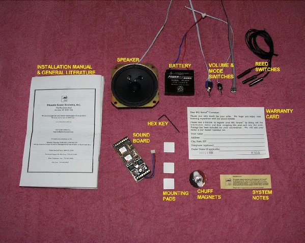
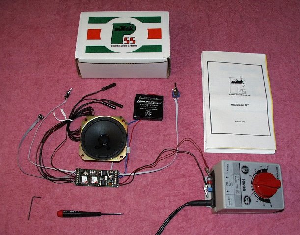
Above are pictured the standard components of a Phoenix Sound System kit. From the left: the instructions and general literature, 3" speaker, sound board, 6V battery, hex key and 3 mounting pads, volume and option switches, warranty card, magnets, and reed switches.
Note that this kit seems to show a change in the style of chuff trigger magnets. Phoenix kits most generally come with a set of plastic compound magnets that were used to trigger the chuffing action. This kit instead came with a set of small, round rare-earth magnets. I must say that this change is for the better. I usually replace the compound magnets with rare-earth type.
I strongly recommend that the warranty card be filled out and sent in. Taking the time to do this is well worth the effort, and can expedite matters if problems arise. Another effort that will make problem handling easier is to gain a good understanding of the sound system and its general operation.
A Tour of the Sound Board: "Big Sound 97"
The Big-Sound 97 or DCB97 as Phoenix refers to it, is the newest style or model sound system that Phoenix offers. The DCB97 offers a better low-power sound output than its predecessors -- the ability to be used at very low operation voltages (as low as 4.5V) and even lower when coupled to one of Phoenix's "Big-Boost" add-on systems. The DCB97 also allows for real-time bell and whistle functions for R/C and DCC control railfans. This "real-time" option was not available in earlier boards, and note that "real-time" functions must be requested when ordering. The following is a brief look at the DCB97 soundboard that is supplied in this kit.
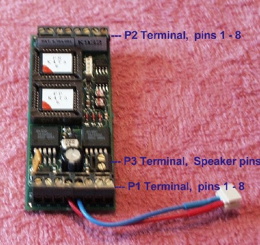
The DCB97 is a compact all-in-one system whose dimensions are 3-3/8" long by 1-1/4" wide by 5/8" tall. The board has three terminal strips on it, P1, P2, and P3 as shown in the photo above. These three connection points provide the board's interfacing with all of its external devices and power sources, such as the speaker, battery and function triggers. Understanding these connection points is paramount to properly installing this sound system. The following links contain descriptions of the three terminal strips and their connection points:
Next, turn your attention to the picture below, and the heart of the DCB97. These are the actual sound chips. They give the system its specific sound or personality. There are two sound chips to a board, a "FS" and a "FP". Both chips are needed in order for the system to function properly.
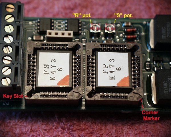
Note the two chips' placement and their orientation in each of their sockets. The red corners are mated to the corner of the chip socket with the placement arrow (corner marker). This chip set gives the board its specific personality. That personality can be change by simply changing the chipset (both FS and FP).
To remove a sound chip, simply insert the hex key supplied with the kit in either of the key slots marked in the picture above and gently pry the chip loose. Because of the careful handling needed, I personally do not recommend changing chips on a steady basis. However, Phoenix acknowledges this practice in the use of sound cars, and sells extra chip sets for the purpose.
The last features on this tour of the DCB97 board are the "R" and "S" potentiometers (adjustable resistors or pots). The R pot. and the S pot. are shown in the picture above. These two pots are only used on a steam sound system when the AutoChuff function is active. The R pot controls the chuff rate and the S pot controls the chuff's start voltage. If you are using the chuff trigger and/or have the voltage controlled, AutoChuff feature disabled, then these pots will have no influence on a steam sound system's operation.
In the setup and operation of a diesel sound system, these pots play an important roll in setting certain sound sequences. The S pot determines the motor start-up and shut down sound sequences. The R pot is slightly adjusted to control diesel motor sound's acceleration and deceleration rate sound levels.
Understanding Reed Switches and Their Uses
A reed switch is a small switch that will close or open when within effective proximity to a magnet or other EMF source. Reed switches are a common method of on-board accessory control for the model-railroading hobby. Many OEM and after-market sound systems use reed switches to control or trigger sound events and/or sequences; it is common for reed switches used for these operations to be referred to as "Function" triggers. Examples are the chuff trigger, whistle trigger, and bell trigger. The photo below shows some examples of the different types of reed switches commonly used.
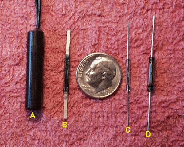
The reed switch above that is marked "A" is the same sealed type that is included in the kit from Phoenix. The "B" switch marked "B" is the flat - plastic style as used by LGB in their older, sound-equipped locos. The reed switches marked "C" and "D" are like new ones used by LGB. I do not recommend using either "C" or "D" style reed switches due to the fact that their cases are composed of glass ampoules, and they require careful handling during installation and operation.
I recommend the "B" style as the best overall and the one I use most generally. Obviously, since the "C" and "D" styles require careful handling, I try to avoid using them. Although the "A" style is always included in the Phoenix kits, quiet a few of the people I have done installs for dislike the site of them on the bottom of their locos and/or sound cars, and are willing to pay extra to have the smaller reed switches installed. The "A" style is also too bulky for use as a chuff trigger inside virtually all G scale, loco drive units.
In the installation portion of the K-28 article you will be shown the method used to install "B" style chuff, bell, and whistle triggers on the K-28.
One closing point about a reed switch is that it is only as good as the magnet(s) that is being used to actuate it. I strongly recommend the use of good rare-earth magnets, especially when used to actuate chuff triggers.
Changing Operation Modes (The DIP-Switch)
Previously, in the section of this article covering the DCB97's P2 terminal connections, we discussed the system's different modes of operation. The operations modes are controlled by four small switches that are all made together in a small unit called a DIP. One DIP, commonly referred to as the DIP-Switch, is generally supplied with every Phoenix system. This DIP-Switch's switches, marked 1 through 4, are used to control the sound system's mode of operation. The link below shows examples of the DIP-Switch's setting for the 5 different modes of operation:
When connecting the DIP-Switch to the sound board, remember that the red stripped lead is ground and should be connected to terminal #8 on the P2 terminal strip.
Please note that the DIP-Switch does not have to be installed if the sound system is to always remain in the "Normal" operations mode.
Speaker Selection
Phoenix offers a line of good, quality speakers. If no specific speaker type is requested, then you will receive their default speaker size for the type of kit ordered. If you are installing a sound system in a boxcar or tender, then the factory-selected, default speaker will usually be the best choice for the installation; the same is generally true for most diesel installs as well. However, for custom, on-board steam engine installations that are not covered by any of Phoenix's special kits, like those for the Bachmann Shay, Climax, and Accucraft Goose, I would suggest a little preplanning. Pre-select the speaker you think is best. And note that you will have to request a special size speaker at the time of order. For some installations I have had to use some third-party speakers. Please note that the system's speaker impedance must be 8 Ohms in order for the systems amplifier to function properly. The use of single, 8-ohm speaker is the general rule. If multiple speakers are to be used then their final overall impedance, again must be 8 Ohms.
Sound System Mockup Test
I have made it a practice, and personally recommend to always bench test a new sound system before you start the installation process. I even recommend doing this and thoroughly testing the system prior to mailing in the warranty card. By performing this task you will make sure you have a 100% functional sound system before you even touch the loco, tender, or boxcar you purchased it for. If you find that something is not right or if a part is found to be missing, then you can take the necessary steps to correct the problem without any down-time for your rolling stock.
The picture above shows the K-28's sound system put together and connected to a power supply. All that is needed to perform this task is a clean place to setup and work, an appropriate power supply, a set of power jumper leads, and a screw driver. For this test you may want to set the DIP-Switch so that the sound system will operate in the DEMONSTRATION MODE (see above).
When you first startup a new sound system, is that you may find the systems battery to be flat, or in need of charging. Applying between 7 and 8 Vdc to it for about a half-an-hour charges the battery. This should charge the battery up enough for a test or two. There is more on battery charging in the later section called "Test Running".
A standard "Steam" sound system wiring diagram is provided by Phoenix on the back of the Big Sound 97 manual, or you may also refer to the wiring diagram below. The diagram below was created specifically to represent the sound system, as it will be used in the K-28 installation.
The wiring diagram above is configured for standard steam sound. However, this diagram differs from the one issued in the manual in two ways. The first difference is that the Doppler function's reed switch has been replaced with a "Canyon-Chuff" on-off switch. This is an add-on feature that is being used in the K-28 installation, but not in the Mogul installation. As for the Doppler effect function, I do not normally even install it, and have had not requests to since I started doing installations professionally. The second difference is the added "battery disconnect" on-off switch installed on the "+" side of the battery inputs. I use this battery disconnect switch modification on ALL of my installs. This switch breaks power between the battery and the sound board. This modification will stop the sound system from running down the battery when stored for long periods of time. This will also help extend the life of your sound system's NiCad battery. Just remember to turn the disconnect switch to the "ON" position prior to running and to the "OFF" position when storing.