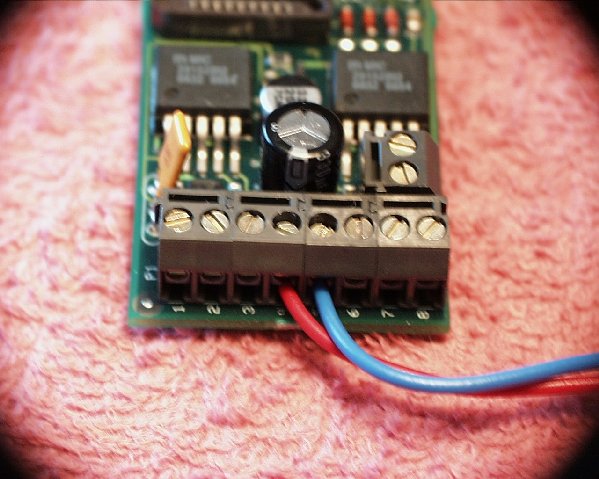
P1 TERMINAL STRIP
Pin #
Connection Description
1
Track Power - Negative, for LGB fans this is the "Blue" lead
(see note 1 below)2
Track Power - Positive, for LGB fans this is the "Red" lead
(see note 1 below)3
Jumper, for using Big Boost kit or 9V battery
(see note 2 below)4
Battery Power - Positive (red lead), 6Vdc normal, 12Vdc maximum voltage
5
Battery Power - Negative (blue lead), 6Vdc normal, 12Vdc maximum voltage
6
Volume Control - Volume Increase, outside switch lead
7
Volume Control - Common, center switch lead
8
Volume Control - Volume Decrease, outside switch lead
Note 1
In the initial forward-movement sound sequence the engine should make two toots of the horn for forward and when in reverse, three toots. This is controlled by the polarity of the voltage applied to these two track power connections. So, if you get it wrong you will have to go back in and swap these two leads around.
Note 2
If you use a Big Boost kit or decide to use a 9V NiCad battery instead of the 6V battery that comes in the kit, you will have to place a jumper wire from 3 to 5 on the P1 terminal strip. Not including this jumper will make the system board treat the battery as though it was the 6V type, this will cause premature failure of a 9V NiCad battery. Want to use a 9V battery to save space - you can get one at Radio Shack!